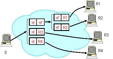
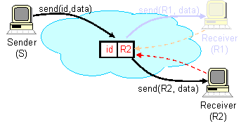
This level of indirection decouples the act of sending from the act of
receiving, and allows i3 to efficiently support a wide variety of
fundamental communication services.

3 Anycast
i3 provides support for anycast by allowing applications to
specify a prefix for each trigger identifier. Packets are then matched
to the identifiers according to the longest matching prefix rule. In
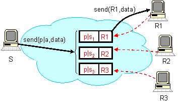
the figure below, receivers Ri (i = 1, 2, 3) insert
triggers whose identifiers share a common prefix p. A packet
with the identifier p|a (where p is the prefix and
a is the suffix) is matched according to the longest prefix
rule and forwarded to the corresponding receiver (in this case
receiver R1). Receivers can choose suffixes to implement
different anycast policies. For example, if the suffixes of all
triggers and packets (requests) are randomly chosen, this scheme
provides load balancing within a factor of log N, where
N is the number of receivers. Similarly, if suffixes encode the
host locations (e.g. zip code where the host which inserts a
trigger or sends a packet is located) the packets will be delivered to
a nearby receiver.

4 Service Composition
To provide support for service composition, i3 allows
applications to replace an identifier with a stack of
identifiers. Figure (a) shows how a sender can request that
all its packets to be forwarded through an intermediate service point
(a transcoder T, in this case) before they are delivered to
their destination, receiver R. In particular, transcoder
T inserts a trigger idT, while sender
S sends packets with the stack (idT, id).
Each packet is forwarded according to the first identifier in its
stack, idT, to the transcoder. After processing the
packet, the transcoder pops the identifier at the top of the stack,
idT, (so now the stack of the packet consists of
only one identifier id) and forwards the packet to receiver
R via trigger (id, R).

Figure (b) illustrates how the receiver can control the packet
processing. In this case, receiver R inserts a trigger, (id,
(idT, R)); note that the second field of the
trigger is a stack of identifier. When a packet with identifier
id matches this trigger, the packet's identifier is replaced
with the second field of the trigger, the stack (idT,
R). Next, the packet is forwarded to transcoder T,
which pops the top of the stack, idT, and then sends
the packet directly to receiver R.


