How i3 Works
Here we give a brief description on the current implementation of
i3. Section 1 explains the baseline
implementation, Section 2 discusses some
simple optimizations, while Section 3 presents
a proxy based solution for supporting legacy applications on top of
i3.
An instantiation of i3 is currently running on the Planetlab testbed. The set of
i3 servers that are currently up is available here.
i3 is implemented as an overlay network consisting of a set of
servers across the Internet. We use the Chord protocol to route
in i3. In a nutshell, Chord partitions a circular identifier
space (called the Chord ring) across the servers in the system. Each
server is associated a unique identifier in the Chord ring. Then a
server with identifier id is assigned a contiguous region
[id'+1, id] in the Chord ring, where id' represents the
identifier of the server that precedes id in the Chord ring.
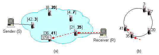
The figures below shows an i3 system consisting of five
nodes with identifiers 3, 7, 20, 35, and 41, respectively. Figure (b)
shows where are these servers located on the Chord ring, while Figure
(a) shows the intervals in the Chord ring assigned to each server. For
example, the server with identifier 35 is assigned the interval [21,
35] as the server that precedes it in the Chord ring has the
identifier 20.

A trigger with identifier id is stored at the node which is
responsible for that id. The figure above shows how a host
(R) inserts the trigger (37, R) into i3. Host
R sends a trigger insert message to an i3 server it
knows about (in this case server 35), from where the message is
forwarded via Chord to the server that is responsible for identifier
37, i.e., server 41. Finally, server 41 stores the trigger.
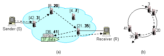
The following figure shows how another host (S) sends a
packet with the same identifier, 37, and how this packet is delivered
to the destination. Similarly to the trigger insertion operation,
S sends the packet to an i3 server it knows about,
server 3, in this case. Server 3 then uses Chord to route the packet
to server 41, which is responsible for identifier 37, where the packet
is matched with the trigger and forwarded to host R. Note that
Chord ensures that it takes O(log N) intermediate hops to route
any message to the server responsible for that message identifier,
where N represents the number of servers in the network.

While Chord ensure that any message visits no more than O(log
N) servers, this number can be still prohibitive in a large
i3 network, especially if the visited servers are far apart. To
alleviate this performance problem, i3 employs two simple
optimizations:
- Caching After a packet reaches the i3 server
responsible for its identifier, the sender can cache that server and
send all the subsequent packets to the server. In the figure above,
host S caches the IP address of server 41, and send all
subsequents packets with identifier 37 to the server. This way, each
of the subsequent packets visits only one i3 servers before
being delivered to the destination.
- Location-aware triggers While caching reduces the number
of i3 hops to one server, routing can be still inefficient if
that server is very far away from the sender and the receiver. For
example, imagine that the sender is located in Berkeley, the receiver
is located in Stanford, and the i3 server is located in
London. In this case, the packet will travel across half of the world
before being forwarded back to a destination that is only 40 miles
away. i3 addresses this problem by having the sender and the
receiver exchanging a pair of location-aware triggers and then use
these triggers for communication. Consider the example above, and
assume that the closest server to host S is server 3, and the
closest server to host R is server 35. In particular, host
S can insert a trigger that is stored at server 3, e.g.,
(1, S), and send identifier 1 to R piggybacked in the
first packet. In turn, host R can chose a trigger (30,
R) that is stored at server 35 and send it to host S via
S's trigger. From now on, host S can send packets to
R using identifier 30, while host R can send packets to
S using identifier 1. In i3 the location aware triggers
(1, S) and (30, R) are also called private
triggers, while trigger (37, R) used to initially contact
R is called public trigger.
The current distribution of i3 includes a proxy-based solution
that allows unmodified applications to run on top of i3. A
brief description of the architecture and the implementation of this
proxy is available here.


